| Applicable Versions | NetSim Academic | NetSim Standard | NetSim Pro |
| Applicable Releases | v14.4 or Higher Versions |
NetSim provides a comprehensive graphical environment for modeling, configuring, and simulating complex communication networks. Using the Internetworks module, users can design network topologies consisting of routers, switches, wired and wireless links, and end devices, while configuring routing protocols, traffic applications, queuing disciplines, VLANs, and network performance parameters.
NetSim also provides detailed performance analysis through packet animation, simulation metrics, packet trace, plots, and logs, enabling users to study network behavior and protocol performance effectively.
Consider the following network scenario created using the Internetworks module in NetSim.
Steps followed to create the network scenario:
1. From the NetSim Home Screen, click on New Simulation and select Internetworks.
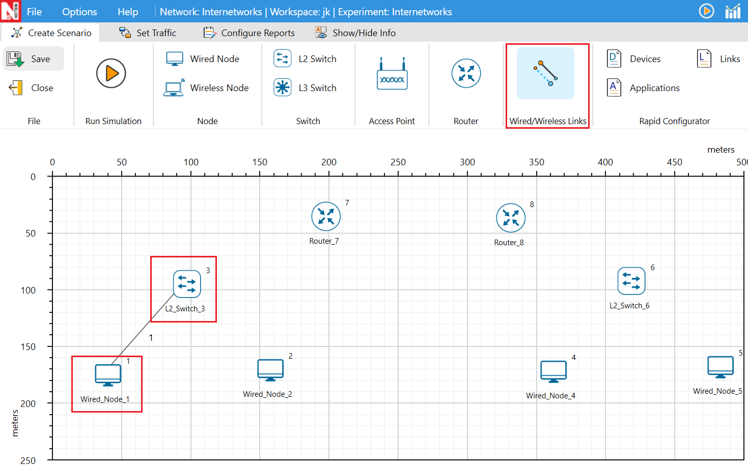
2. From the device panel at the top of the GUI, select the device and drop it onto the simulation grid.
3. To connect devices, select the required link type from the device panel, left-click on the first device and release the mouse, and then click on the second device and release the mouse again to establish the connection. Note that right-clicking anywhere in the workspace may temporarily hide wired links. Also, avoid accidentally moving devices while creating links by ensuring the mouse button is properly released after each click.
4. Each device and link in NetSim can be configured individually. To configure a wired link, right-click on the link ID and select Properties.
5. In the Link Properties Window that appears various properties of a wired link such as Link Speed (Mbps), Bit Error Rate, Propagation Delay etc can be configured.

6. In case of wired links between routers (WAN interfaces), link failure model is available, where the link up and down time can be specified to model link failure at specified duration during the simulation:
7. To configure the router properties, right click on it and select properties. Routers in NetSim support OSPF and RIP protocols which can be configured in the Application Layer section of the Router properties Window
8. Router also supports Static route configuration and Access Control List configuration (ACL) in the Network Layer Section.

9. In the WAN interfaces of the router, Scheduling and Queuing type can be set.
10. To configure a Switch, right click on the switch and select properties.
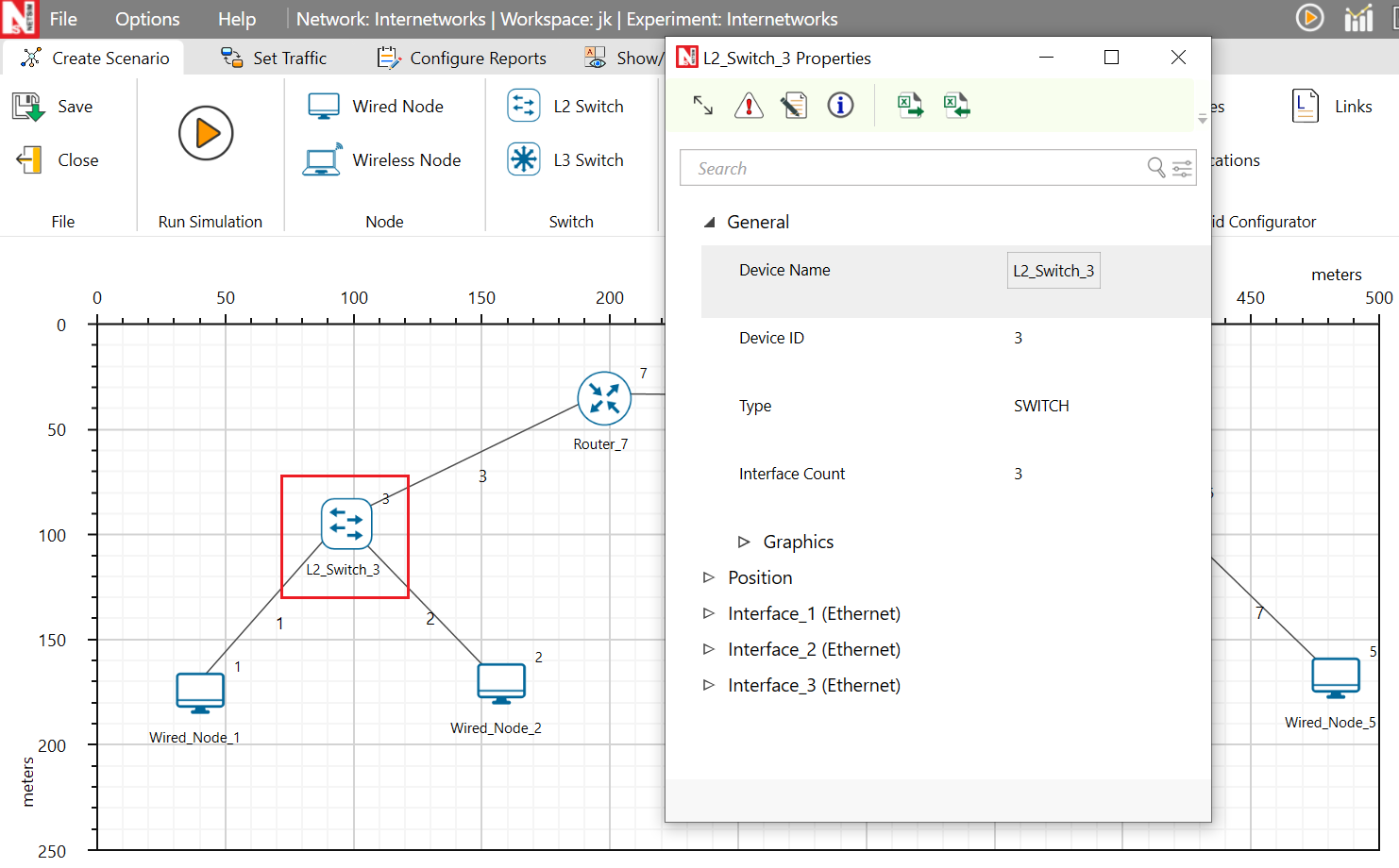
11. The Buffer Size, Switch Priority, Spanning Tree Protocol Cost, Switching Mode etc can be configured in the Data Link layer property seciton of each of the interface that a switch has.
12. Switches also support VLAN configuration which can be accessed by setting the VLAN status to TRUE
13. After configuring the devices and links, application traffic can be modeled by clicking on the Set Traffic tab.
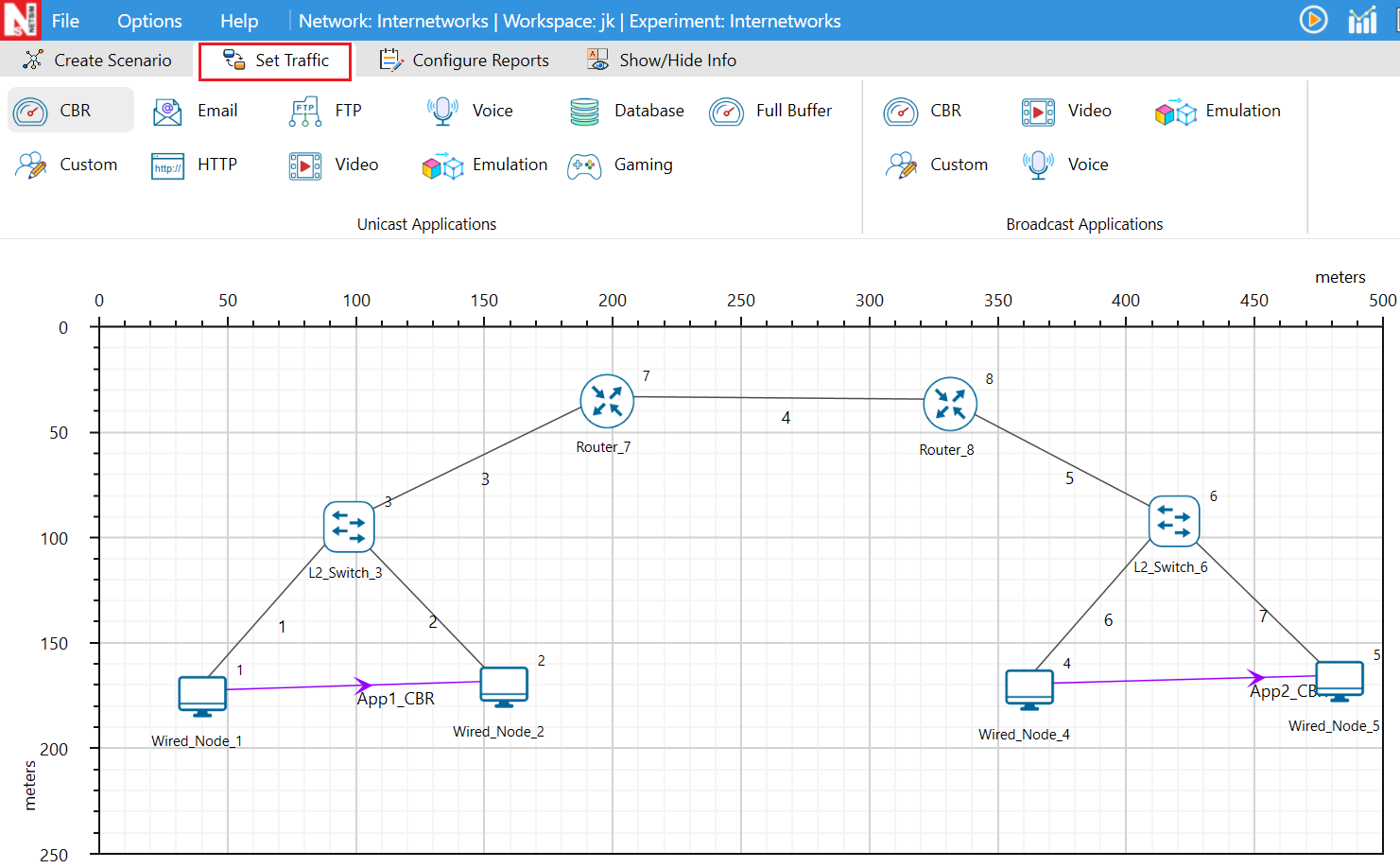
14. NetSim supports Unicast, Multicast and Broadcast traffic with support for various application models such as CBR, HTTP, FTP, Voice, Video, Database, Full Buffer, Interactive Gaming, etc. You can configure multiple applications between different devices in the network. Various properties such as source id, destination id, start time, end time, encryption, priority etc can be configured for each application.
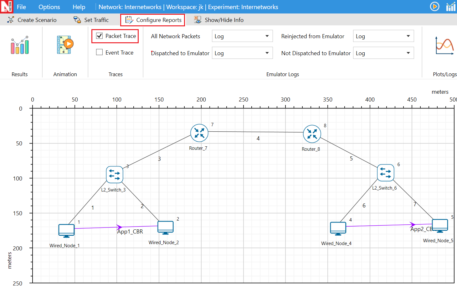
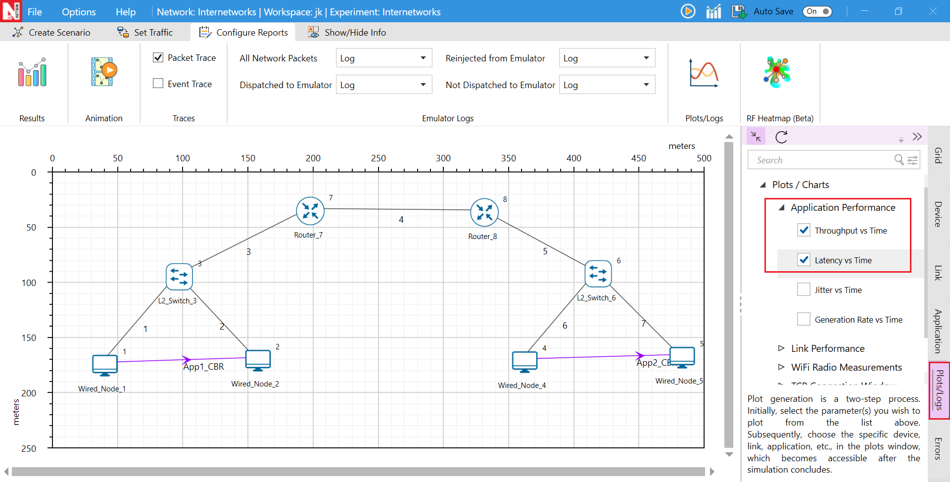
15, Before running the simulation, advanced options such as Packet Trace and Network Plots can be enabled. Packet Trace can be configured from the Configure Reports tab, while Network Plots and Logs can be configured from the Plots/Logs panel available on the right side of the GUI.
Packet trace:
Network Plots
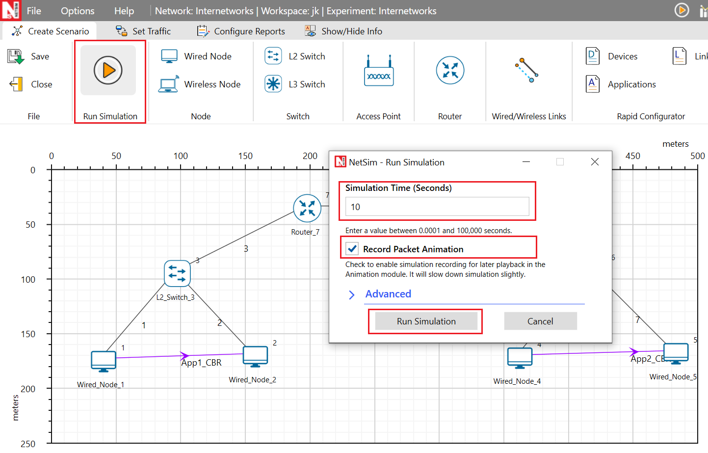
To execute the simulation, click on Run, specify the simulation time, and enable Packet Animation if packet flow visualization is required.
16. After the simulation is completed, NetSim provides the Packet Animator and Results Dashboard, which help users visualize packet flow.
17. The Simulation Metrics window provides detailed performance statistics such as Application Metrics, Link Metrics, Queue Metrics, Plots, and Logs, which help users evaluate and analyze overall network performance in detail.

NetSim also includes several built-in examples and experiments that can be accessed from the Examples menu on the Home Screen. Each network technology comes with featured examples and dedicated documentation, which can be opened directly by clicking on the corresponding Book icon.
For more details on creating the network, configuring traffic models, plots, and logs, refer to Section 2, NetSim GUI, in the NetSim User Manual: NetSim_User_Manual.pdf


